 <
<


If you are like many clients of Architects, particularly those for whom you are having a house designed, you probably have questions about how to read the Architect’s documents and what is located in them.
And you may want more than a single opinion as to what should be in the documents. Here is one public resource link on the WIKI platform: WikiHow to read an Architect’s Drawings
Here’s another from the Army: Army Blueprint Reading
Now, what follows is the ArCH organization’s report on How to Read an Architect’s Drawings. ArCH: Architects Creating Homes represents, supports and endorses the best practices for licensed Architects who design homes.
HOW TO READ ARCHITECTS’ DOCUMENTS,
LEVEL OF DETAIL,
DRAWING ORGANIZATION
First and foremost: EVERY Architectural firm has its own methods, systems and standards. No given firm will have its practices repeated identically at any other firm, even in firms with branch offices of a larger company. Regional variations are inevitable. So: do not look for there to be any one, overall “way” of doing things. Practices referenced herein have been found to exist at firms practicing throughout the USA. Some residential drawing sheet sets can be less, others can be 20, 30, 50 or over 100 sheets. This depends on the project, office standards and level of detail that each Architect feels is applicable to do a proper job for each project.
1. DRAWING NUMBERING:
Many Architects number their drawings with prefixes that represent the type of items being shown (or work trades) on the drawing being numbered.
G SHEETS: For instance, G series drawings are often found at the front of the Architect’s drawings, which represents “General.” Typical G drawings might be a G-1 Title sheet, G-2 Drawing Index and G-3 Site Location Map, Abbreviations and General Information. There may also be more G sheets, depending on the project. Some Architects may instead number their sheets G101, G102, etc.
A SHEETS: A series sheets are almost always for “Architectural.”
For instance: A2 sheets are often used to refer to Site or Civil work: A2-1 Overall Survey, A2-2 Intermediate Survey, A2-3 Detail Survey, A2-4 Overall Site Plan, A2-5 Intermediate Site Plan, A2-6 Detail Site Plan. Some Architects may number these sheets A201, A203, etc.
A3 sheets are often reserved for Floor Plans: A3-B Basement Floor Plan, A3-1 First Floor Plan, A3-2 Second Floor Plan, A3-3 Third Floor Plan, etc. Some firms may instead number their sheets A301, A302, etc.
A5 sheets are commonly used for Roof Plans: A5-1 Roof Plan. There may be more, depending on the project. Some Architects may number these sheets A501, A502, etc. or otherwise.
A4 sheets may be used to depict Ceiling Plans (actually “Reflected Ceiling Plans”, as the orientation is as viewed looking straight down, as if the floor was a mirror). There is no set convention as to whether or not ceiling plans are required or not. It depends on the LOD (Level of Detail) the particular Architect feels is appropriate for the particular project. Some Architects may number these sheets A401, A402, etc. or otherwise. Not all home design projects have ceiling plans.
A6 sheets are typically for exterior building elevations: A6-1 Front Elevation, A6-2 Right Side Elevation, A6-3 Left Side Elevation, A6-4 Rear Elevation. Often, the compass directions are also added to each elevation name so that the people working on the project understand the solar & wind orientations. Some firms may number these sheets A601, A602 or otherwise.
A7 drawings are often used for Building Sections. A7-1 Front to Back Main Building Section, A7-2 Left to Right Main Building Section, and so forth. There is no set number of Building Sections, nor any specific requirement. Building Sections are like taking a big knife and cutting into a layer cake (the building/home) and looking at it sideways. Architects, since Leonardo DaVinci’s time have used this method to illustrate how the projects components fit together. Some Architects may number these sheets A701, A702, etc. or otherwise.
A8 sheets are often used for Wall Sections, which are blow-ups of the walls you see in the Building Sections (often), or the walls illustrated can be from other areas the Architect feels he or she should show. There is no set scale, although, wall sections are usually at a more detailed view, to allow people to see the various components better. Some Architects may number these sheets A8-1, A8-2, etc, or A801, A802, etc. or otherwise.
A9 sheet may be used for Schedules, such as: A9-1 Door Schedule, A9-2 Finish Schedule, etc. Some Architects provide Window Schedules, others do not. Some Architects may indicate, particularly in residential projects, the nominal size of doors & windows on their plans and elevations, then require the Contractor to obtain a shop drawing list from the selected window manufacturer BEFORE framing the window and door rough openings. Why: Because there is no set standard between window and door manufacturers at the present time as to what the exact rough opening sizes required are for any particular indicated nominal dimension. For instance: an Architect may indicate a 3′-0″ x 4′-6″ window on his Floor Plan. Often the Architect means that this window is approximately 3′ wide x 4′-6″ tall. Does this mean that the framing crew should make the Rough Opening that size? No. Why? Because each window manufacture and each door manufacturer has its own exact dimensions WHICH VARY from manufacturer to manufacturer. And to further complicate matters, quite often the Builder will decide to substitute a different window or door company than what was specified by the Architect, meaning that even if the Architect did indicate a precise rough opening size for that particular specified window or door manufacturer, the second the Builder switched to another manufacturer, that means that the exact rough opening dimensions changed. And this happens on most projects, built all over the USA and world.
A10 Sheets may or may not be included and can focus on a variety of topics.
A11 may be used for Casework & Equipment, like cabinetry elevations and specialty appliances and the like that are not otherwise depicted on the floor plans, or for which you may want a higher level of detail, like at at 1″ scale, for instance, although there are no hard and fast rules. Some Architects may number these sheets A11-1, A11-2, etc. or: A1101, A1102, etc. or otherwise. Some Owners may or may not want to pay the Architect to produce the Kitchen and Bathroom and other interior elevations, although it is recommended. This can be made optional to the Owner by the Architect.
A12 for some Architects may be used for Master Details, or for others, for Furnishings. Once again, there is no defined required numbering convention mandating any particular number. Some Architects may number these sheets A1201, A1202, etc. or otherwise. Some firms may number their sheets in this fashion: A12-3 sheets for Concrete Details, A12-4 for Masonry Details, A12-6 sheets for Framing Details, A12-7 sheets for Roofing & Flashing Details, A12-8 sheets for Window Details, etc. There is no set standard, but Architects strive to control the information to become more understandable. For instance, the suffixes indicated above in fact comply with the traditional CSI (Construction Specifications Institute) numbering system wherein Division 3 in Concrete, Division 4 is Masonry, Division 6 is Wood & Plastics, Division 7 is Thermal & Moisture Protection, etc., while A12 represents the Master Detail category series of where to find these drawings in the set. Some firms may number these sheets A1201, A1202, etc.
A14 may be used by some Architects for Master Numbered Drawing Note lists. For instance: A14-1 Master Numbered Drawings Notes, A14-2 Master Numbered Drawing Notes, etc. In the past, many Architects put numbered drawings notes in a column, often along the right side of each of their sheets, just to the left of their title block. However, the management of these notes, from sheet to sheet can become demanding and confusing, if the same number of note is used for different things from sheet to sheet, so: the newer convention is including a single (or however many) concentrated source sheet for the various note definitions, consolidated into one place, onto one single sheet if possible, or on however many sheets is necessary. Some firms may number these sheets A1401, A1402, etc.
Why numbered drawing notes are used by Architects: because using a text note right on each drawing results in a cluttered drawing than can become hard to understand. Decades ago, Architects and Engineers and other trades discovered that by the simple method of using columns of notes in a particular place reserved for text notes and by numbering the notes, they could use those much smaller and compact numbers throughout the drawings, resulting in a much clearer and cleaner set of drawings. There are so many technical components these days to described, that it is just about impossible to adequately indicate them with text-only notes used around each drawing. More will be devoted to this subject in a following item below.
A15 sheets may be used by some Architects for their specifications. For instance: A15-1 Specifications, A15-2 Specifications, etc. Why do Architects provide Specifications: because Specifications indicate the codes, quality level, material types, thicknesses, model numbers, possibly colors, weights, and other material and product characteristics that make your project a reliable and quality construction effort. Some Architects provide their specifications (also referred to as “specs”) right on the drawings, for instance, on the A15 sheets, for instance (or other drawing series number), or the Architect may locate the specs in a separate book, that are expected to be used in conjunction with the drawings to build the project. Other Architects may only included minimal specification information in their numbered drawing notes. This is really a matter of preference for each Architect and what they feel represents the best practice to provide a quality set of documents that results in the project being properly constructed.
Variations of “A” sheets: for instance: some firms may use “AD-XXX” for Architectural-Demolition, or “AE-XXX” for Architectural- Existing. Other firms may try to give more information in the sheet numbers instead using: A3-1-dem (for Architectural Floor Plan, Level 1, Demolition. Or: A3-1-ex (for Architectural Floor Plan, Level 1, Existing). Other firms may use: AD-301, AE-301 or other variations.
S SHEETS: are almost always for Structural Engineering drawings. These are typically done by a licensed P.E. (Professional Engineer) or in some states S.E. (Structural Engineer) or other professional designation per each State’s standards. Sheets are often numbered by the engineer as S-1, S-2, etc. Sometimes the Architect will request that the Engineer follow the Architect’s sheet numbering standards, although this is not required. Structural Engineering is where you might commonly find Foundation Plans, Floor Framing Plans, Roof Framing Plans, Structural Details, Structural Notes and related structural information. Some engineering firms will try to parallel the Architect’s numbering systems having everything but the “S” prefix similar to the Architects, although this may or may not happen on all projects.
E SHEETS: are typically for Electrical information. It is unusual for an Electrical Engineer to do this on a residential project. Normally, the Owner is given the option of having the Architect create Electrical Schematics, which depict the location of built-in light fixtures, fans, switches, electrical panels, Information Systems panels and computer and TV outlets and related items. There might be an Electrical keynote sheet, possibly numbered EG-1, then E-B, E-1, E-2, etc. for the Basement, 1st Floor, 2nd Floor, and so forth.
P SHEETS: it is extremely rare for there to be Plumbing Drawing sheets for a house. This is something that is typically handled by each Plumber in the field, however, on certain projects, some Architects and consultants may include this (even though not usually).
M SHEETS: it is very unusual for there to be Mechanical Sheets for a house. This would be for HVAC (Heating, Ventilating & Air-Conditioning) work. Possibly for some high-end, large and complex project, this might happen. Usually, the Architect has resolved the spacial requirements to allow for the ductwork and equipment to be located throughout the project into specific locations, possibly, but rarely is actual ductwork indicated on the drawings. Architects often will depict rough equipment locations for exterior heat pumps and.or compressors and also for split system AHU (Air Handling Units) within the structure and also may have resolved how the main duct routes get back to the AHU. But not too often do you see actual M-1, M-2, etc. drawings within a set of home drawings. Normally the HVAC subcontractor designs his ductwork in the field (meaning on the project location) while installing the system.
There can be and are many other sheet numbers used for a variety of things, like special interiors work and the like.
2. LEVEL OF DETAIL, NUMBER OF SHEETS IN A SET OF DOCUMENTS FOR A HOUSE:
This is something that only each Architect can determine for each of their projects. There is no right or wrong answer for this. Some projects that Owners might believe should be accomplished on 10 sheets may actually require 30 sheets or more, depending on what the Architect discovers about the project. And projects that someone without a license to design that might produce 25 sheets might really require 40, 50 or 75 sheets to do properly. Having an Architectural License carries with it the legal responsibility to protect the Health, Safety & Welfare of the public (including the Owner). The Architect is required to act in the best interests of not only the Owner, but future possible Owners and others from the public in general that may encounter the project. However, Architects may also pull back from what others involved in a project might want to do. For instance: an Interior Design person might want to produce 100 sheets of casework details and the Architect might feel that is overkill, particularly if the Owner doesn’t want to pay for those services. So, the Architect provides what he or she feels is appropriate for each project.
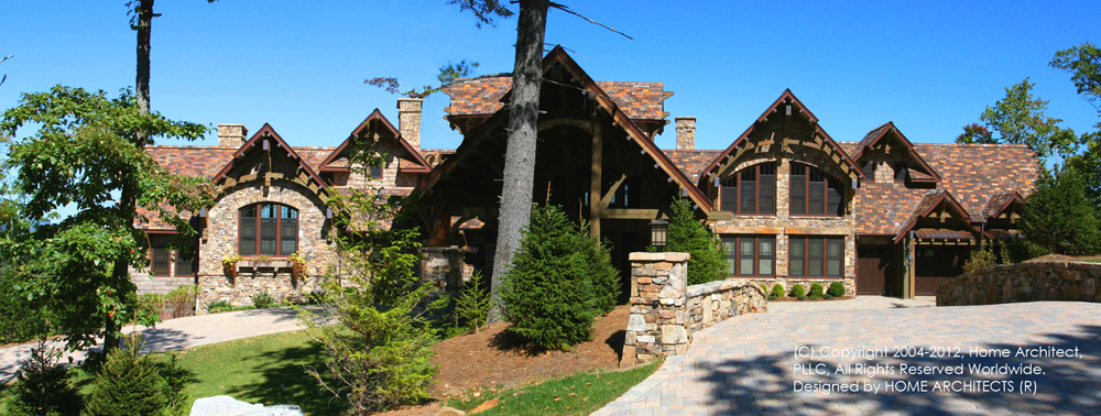
As an example, creating a small to medium-sized home on rural acreage might sound like only a few sheets of drawings might be required. Let’s take a look at that, then add up the total:
First: you will need a survey. And because the survey encompasses about 25 acres, and there are some complex driveway turns and condition leading to other people’s properties, you are going to have to scale the Surveyor’s drawing to 3 separate sheets to make them readable when printed on 24″ x 36″ (or whatever sheet size used). So that will be:
A2-1 Overall Survey
A2-2 Intermediate Survey
A2-3 Detail Survey
Okay: so we now have 3 sheets.
But wait, there are several other standard sheets that become part of the set:
G-1 Title Sheet
G-2 Drawing Index
G-3 Site Location Map, Abbreviations & General Information
So now we are up to 6 sheets and we haven’t even gotten to the Architecture. Let’s keep going:
How about the Architect’s Site Plan, showing where your driveway is located, well, septic field and other sitework? And if the driveway is particularly long, the Site Plan might need to be shown and 2 different scales:
A2-4 Overall Site Plan
A2-5 Detail Site Plan
Now we are up to 8 sheets of drawings.
Okay, now we’re rolling! Let’s see, what’s next?
Well, you want a walkout basement house and you also want a loft over the main level. This could very easily mean the following:
A3-B Basement Floor Plan
A3-1 First Floor Plan
A3-2 Seconds Floor (Loft) Plan
We are up to 10 sheet of drawings.
Next, all Contractors and roof framing company want to see a Roof Plan:
A5-1 Roof Plan
How about what this house is going to look like as you drive up to it and walk around it?
A6-1 Front Elevation
A6-2 Right Side Elevation
A6-3 Left Side Elevation
A6-4 Rear Elevation
There are presently 15 drawing sheets.
Now: how does the house go together?
A7-1 Building Section (Front to Rear)
There may also be additional Building Sections through other areas, like Garages and also possibly Cross Sections (also called Transverse Sections), but let’s just add one more for now:
A7-2 Building Section.
We now have 17 sheets of drawings.
How about some greater detail on the sections?
A8-1 Wall Sections
There could be several sheets of these, but let’s pull back and just include one for now.
That’s 18 sheets total so far.
How about the Finishes and the Doors that go into this house? What are they?
A9-1 Door Schedule & Finish Schedule (however, there could easily be one entire sheet for each of these, but let’s be compact and see if we can shrink the set some)
19 sheets so far.
How about your Kitchen and Bathroom cabinets? There could easily be 6 or more sheets of 1″ scale (or otherwise) detailed elevations of these at this point, in the A11 series. But let’s pass on this for now.
Now for the Architect’s Master Details that he or she uses on many projects, to depict areas that the Architect feels in important:
A12-3d Concrete Details
A12-6-1 Railing Details
A12-6-2 Wall base, shear walls, wind posts, bracing details
A12-7c Flashing Details, Soffits, Wall Type
A12-8a Window Details 1
A12-8b Window Details 2
A12-8d Door Thresholds
Let’s see: we are now up to 26 sheets.
How about the definition of all the Numbered Drawing Notes used on all of the sheets?
A14-1 Master Numbered Drawing Notes (and while this could result in more than one sheet, let’s say we can fit them all on just this one)
And now for the Specifications (which will define the quality, type, thickness, models and other characteristics for your project:
A15-1 through A15-8
We are now up to 35 sheets. We are done with most of the Architectural effort.
The Structural Engineer may have at least 3 sheet, perhaps 4. Let’s say 4.
We are at 39 sheets.
While there may or may not be Electrical Schematic sheets that you want your Architect to produce, let’s take a look at where we are at: 39 sheets of drawings for a fairly compact house of perhaps 2,500 to 3,500 HSF Heated Square Feet. Now that you’ve participated in the building of this set, this may help you, as an Owner, to understand why the Architect needs to include what they do in your project set of documents. Every sheet has a purpose. If this house was larger, had greater detail and more conditions, it would be easy to double the number of drawings to properly depict the various features. However: there may in fact be small, simple projects (like a small, focused renovation), that could possibly be handled on as few as 3 to 5 sheets; it all really depends and your Architect is the professional who decides on the approach that they feel is appropriate. There is no right or wrong as to the LOD (Level Of Detail).
3. READING THE ARCHITECTURAL & OTHER SHEETS OF DRAWINGS:
Printing, Plotting, PDFs:
These days, Architect may be e-mailing you PDFs of their drawings. You can choose to print those or simply read them electronically on your computer monitor. The advantage of reviewing them electronically is that you can zoom in to see finer detail, and save the cost of printing. If you do decide to print out the documents “full size” that will usually mean having a printing service in your town charge you to plot the drawings out on 24″ x 36″ sheets, or whatever size sheet your Architect uses. Sheet sizes can go up to 30″x42″ and even 36″x48″, although many firms use 24″x36″. Or you can pay for Architect to plot out and send you the documents. These are costs covered in your agreement with your Architect under “Reimbursable Charges”.
Dimensions:
Okay, once you have your printed paper drawings or are looking at them electronically, you need to orient yourself to the scale of each drawing sheets scale. Since not much of the Architect’s work would actually fit on drawings if they were “real world size”, the Architect will scale the plans, sections and other elements to be a fraction of their real size on the drawings. So you need to look at the drawing titles, which the Architect will have under each drawing. The line immediately under the drawing title should have the scale of that specific drawing indicated. For instance: Scale: 1/4 = 1′-0″. This means: that for every 1/4″ that you see on the printed drawing sheet, that represents one real whole foot. To help you and your Contractor understand the specific dimensions of the walls and other elements of your project, you Architect will have indicated many dimensions (particularly for the final Construction Documents which are also called “CDs”). So, you will see lots of numbers running around the outside and through the interior of your project. These numbers will be married to thin dimension lines that will have arrows or diagonal hash marks, or dots, which indicate from where to where the dimension applies. For instance: you may see an overall dimension for your house that reads: 80′-0″. That means that your house will measure 80′ from one side to the other, when built. The same concept applies to all of the dimensions you see on the Architect’s documents. If you want to understand, in general how much distance there is between items not otherwise dimensioned, you will probably have to obtain an Architect’s scale from a drafting supply house. Ask the sales person to explain how to use it. These are often triangular in cross-section, and offer many different scales on each facet of the measuring tool. Also: notice that if you have printed out your documents on 11″x17″ or notebook size or other size that is not the true plotted scale for a 24″x36″ (or other sheet size), that your scale will no longer work, because you will have printed the drawing out at a size other that its intended plot size.
Title Sheet:
This has the basic information of the project like the project title, perhaps a nice image of the what the project might look like when built and perhaps other information. This is like the cover of a book.
Drawing Index:
This includes a list of the drawings included in the set. This will help to orient you and your Builder, as to where things are in the set.
Abbreviations, Site Location, General Information:
This may include a map to the project site from surrounding roadways, contact information for the Architect, Engineer(s), Surveyor and other involved with the project, drafting symbol definitions, and abbreviation definitions.
Survey(s) sheets:
This includes the existing features of your site. You usually do not see things on this that are proposed (with the possible exception of approved septic areas). There may be topographic contours, which illustrate the slope of your ground in certain intervals, the location of your property lines, electrical & phone service locations, water or well locations (if any), nearby roads, and other existing data.
Site Plan(s):
This is often created by the Architect and illustrates, usually proposed site features (and the proposed home) superimposed on top of the survey. There sill be driveways, power and communications lines, water and sewer lines, septic fields and tank and other features illustrated here.
Floor Plans:
The floor plans illustrate what you would see if the roof was removed and you were looking straight down at the house. And you would remove each floor see the level below that. You should not scale a floor plan or any drawing and most Architects have warnings on their documents mentioning this. This is because it is easy to scale incorrectly. The best practice is to use the Architect’s dimensions indicated on the documents. If the Architect is using a CAD or other electronic program, the dimensions are probably “associative”, which means that they are correct and are electronically married to what they are dimensioning, so they are correct 99% of the time. The floor plans illustrate the location of the walls, doors, windows, and much of the other items in a house, such as, but not limited to: kitchen equipment, plumbing fixtures and other items. Although, not everything will necessarily be shown on the floor plans. And let’s talk for a bit about the term “plans.” As you are beginning to understand, there is much more to a set of CDs (Construction Documents) than just the floor plans. So when people say “plans” they may actually mean: Construction Documents. Architects are the best professionals in the world at laying out floor plans. They have been taught how to do this at major University Architectural schools and through decades of experience for people similar to you. The best floor plan layouts come from Architects.
Roof Plan(s):
An Architect’s roof plan is what your roof will look like if you could fly over your house and look straight down on it after it was done being built. Many trades use this plan to help them understand how the roof framing should be created, where plumbing vents should be placed, where ridge lines, valleys, attic vents and many other features need to be placed. The roof plan also indicates the various roof slopes and direction of rainwater on the roof.
Elevations:
Look at these and imagine walking around your house, as if you were looking straight back at the various sides of the built home. These illustrations depict what it is supposed to look like. Since we are focused on CDs (Constructions Documents) you will see elevation lines indicating the levels of the project: Basement, 1st Floor, 2nd Floor and so forth. You will seem notes (especially numbered notes) pointing at various things, like siding, trim, roofing and other items, that inform us as to what the project is to be made of. You will see the general arrangement of doors and windows and roof and other features, showing you and the Builder where these items are to be placed and what they are.
Building Sections:
As mentioned before, a Building Section is like taking a big knife and cutting through your house vertically, then separating the pieces and looking at it sideways. This shows you how the various walls, roofs, foundation walls, floors, framing and other main components go together. This is one of the most important drawings in the set and is almost always complex, with many notes.
Wall Sections:
If you look closely at the Building Section(s) and the Wall Sections, you may notice that some of the Wall Sections have come from the Building Section(s). Meaning: that the wall sections are a larger versions of the pieces and parts shown in the Building Section(s), with added detail and more notes, describing what the various items are and what holds them together, how they are trimmed and the thicknesses and widths of various items. Wall Sections have some of the best detail on a project for how things fit together.
Schedules: Door & Finish:
This (or these) sheet(s) is where you will find the sizes and appearances of the intended doors and the type of finishes to be applied to the interior of the house. In other words, here is where the materials will be indicated for your visible ceilings, floors, walls and wall bases. There may or may not be color included. Typically not, as Owners often prefer to see the Contractor’s material sample boards and choose from those, which can vary significantly from what the Architect specified. Also, there may be Owner Optional Upgrades for doors and finishes indicated here. Any fire rated doors may be shown here, along with comments for any required door closers, such as between a garage and living space.
Casework and Cabinetry Elevations:
If you have paid your Architect to produce these, this is where you will find the cabinetry elevations for your project. This may include Kitchen and Bathroom cabinets, but, in higher-end homes, also possibly include closet cabinets, and perhaps special garage workshop cabinetry. This may be offered as an optional additional service from the Architect to you.
Details:
These will illustrate, at the largest size scale in the set, the close-up arrangements of various conditions the Architect feels are appropriate. There may be, for instance, the entry apron of the sill of a garage concrete slab entrance, railing details, shear wall details, roofing edge and flashing details, window details, door thresholds and others. Read the notes and learn what the pieces do and how it works together.
Numbered Drawing Notes and their evolution:
It used to be that the cutting edge in Architectural Drawings in about 1981 was to have numbered notes along the right side of each drawing sheet and the notes were simply numbered: 1,2,3,4 etc. However, over the decades, this notation system evolved. Contractors complained that the notes, while numbered, didn’t tell them at a glance, what trade that particular note might belong to. So, Architects began to number the notes per the CSI (Construction Specifications Institute), which has various main Divisions of construction work categorized by number. For instance: Division 1 has to do with General, Administrative items. Division 2 = Sitework. Division 3 = Concrete, Division 4 = Masonry, Division 6= Wood & Plastics (framing, counter, cabinets and the like), and so on. Back then, the CSI divisions only numbered 16. Now days, the CSI sections have exploded into about 40 to 50 divisions.
Some large firms adhere to the full 40 to 50 sections, however, most residential Architects have maintained about 16 or so traditional specification section divisions for their numbered notes. This varies by firm. This can be directly linked to the Architect’s specifications. However, let’s consider a couple of Numbered Drawing Notes: 6-442 with a leader line pointing at the edge of the roof overhang might be defined in the Numbered Drawing Note list under Division 6, note “6-442: #2 SYP (Southern Yellow Pine) P.T. (Pressure Treated) fascia.” There might be a numbered note 3-301 on the drawings, pointing at a foundation wall. When you look in the Numbered Drawing Note list, you might find, under Division 3, note: ” 3-301: Painted concrete foundation wall.”
So: today, many Architects categorize their notes into the CSI Division with the prefix of the numbered note and the suffix of the note is a specific identifier of something within that Division. Contractors engage their subcontractors based on these CSI Divsions: there will be concrete subcontractors (Division 3), wood framing crews (Division 6), Mechanical subcontractors (Division 15h), Electrical subcontractors (Division 16) and more. There will typically be around 50 subcontracted trades on about any average new house project. So, anything the Architect can do to categorize Numbered Drawing Notes actually makes the GCs (General Contractors) job easier, by helping him to identify who is doing what on the project, by virtue of the division under which each numbered drawing note is coded.
Now then, it used to be that the numbered notes definitions appears on each and every drawing sheet along the right hand side. However, this resulted in a huge amount of work for the Architect, to keep reproducing these notes and sometimes there could be quality control issues, with a numbered note getting used twice, varying the number from sheet to sheet.
The current trend setting approach is for Architects to have one or two or so main Master Numbered Drawing Notes sheet(s) somewhere in the set of drawings, perhaps in series A14. Here is where the numbered notes are defined in one place and used throughout the entire set. This creates a much more uniform list of notes and less time required from the Architect and more consistent note numbering. Contractors get used to knowing that note 3-301= painted concrete foundation wall, so it would be best if that numbered note remained the same for the entire project. The main key to successful use of this approach is for the Builder to make 2 copies of the Master Note List, one bound in the set, the other loose, so that as people turn through the sheets in the set, the note definition index is lying right there to the side of the set, so that no one has to keep turning back to the sheet with the index.
Specifications:
Here is where the majority, if not all elements of the project are defined in detail, with perhaps, a few exceptions. The idea for this to be the “Bible” of WHAT is being used in the project. The HOW & WHERE is what you will find in the other parts of the set of documents. The specifications generally will adhere to the CSI (Construction Specifications Institute) of Divisions, either old school 16 Divisions or the 50+ new Divisions, or some blend thereof. Architect can make up their own specifications and do, to handle areas of their projects that they wish to define in detail. Some specifications come from the manufacturers of the various products used on the projects, such as roofing, doors and windows, and the other components. Specifications can indicate procedures as well as material characteristics. Advanced firms may number the paragraphs of their specifications in order to link them to the Numbered Drawing Notes and to directly use the numbered spec paragraphs right on the drawings, to indicate to the Builder what is intended and where. This aides the Builder in understanding what trades are to handle what parts of the project and greatly assists in the coordination of the job.
Note: there may be some “old school” construction people that regard such numbering (in the Specifications and with the Numbered Notes) with confusion and suspicion. These folks are gradually being replaced with electronic savvy licensed Contractors who appreciate the built-in coordination accomplished by the Architect. Anyone who “wants to do it their way” instead of how the Architect is depicting it is showing a lack of respect for what the Owner told the Architect they wanted. Better to do business with a Builder that is used to coordinating with Architects and who exhibits a mutual respect for the other team members. Anyone who says: “I don’t need any specs; I’d rather just give you what I want to give you, rather than what your Architect indicates,” is not exhibiting a concern or desire to provide you with what you wish to have built, or what your Architect knows will result in a stronger, more durable and attractive home. Only you, as the Owner, can make the decision to have a quality Contractor who enjoys working with licensed Architects to produce excellent projects for you.
Structural Documents:
These are often accomplished by a Structural Engineer, licensed in the State of the project. These documents typically depict the plan layout of the foundations and foundation walls. This is what the surveyor often will use to create the initial “stake-out” of the project on the site. Also, the engineering documents may indicate the floor framing and roof framing and associated details. Read the notes, look at the drawings. You will come away with an improved understanding of what is holding up your house. If the GC (General Contractor) will be providing pre-engineered structural items like roof trusses, floor trusses and manufactured beams (such as “LVLs”), there is no point in your Structural Engineer re-engineering those. There will be engineers, licensed in the State of the project engineering those prefabricated structural elements: they are required to do so and the GC is required to provide those, along with the other project documents to the permitting authority to obtain the Building Permit. The Architect will coordinate with the Structural Engineer, however, different Architects manage the engagement of the engineer differently. For instance, some Architects will request that the Owner contract with and directly pay the engineer, even though the Architect will manage the process for the Owner. It is a question of liability.
Electrical documents:
First: understand that just because an Architect provides an electrical layout, this does Not mean that the Architect has engineered anything electrically. That falls on the shoulders of any consulting electrical engineer, or more likely to the licensed Electrical subcontractor. To read an Electrical documents provided by the Architect, first look to see if there is any Electrical Legend, which will define the symbols used on any Electrical drawings. Look for wall switches. You will notice that your Architect has likely located them so that they are never behind any door swings and that wall outlets are logically located for your convenience, along with built-in light fixtures, exhaust fans, data outlets and other features. Review this in detail. It is recommended that you pay your Architect to provide this work, which may be an Additional Service.